Jan Timmermans
- Homemade Electric Focuser (EF)
Material
used:
1 Motor, 12V, 120 rpm, gearbox reduction: 1:50
1 worm wheel + cogwheel (= with teeth)1:30
1 Polarity switch 12V
2 jubilee clips
Note: Motor has - after gearbox reduction - 2
revolutions per second. This means that the cogwheel
makes one full turn around in 15 seconds (30 teeth).
Experience Report #1
First the worm wheel needed to be mounted on the axle of
the motor. As the axle of the motor was too thick for the
worm wheel, the diameter of the axle needed to be reduced.
I clamped the motor in my workbench, so that it could not
move (but it could run!)
I applied 12V DC (from my car battery charger) to the
motor to make it running. Then I used a file to reduce
the diameter of the axis. This went rather easy. I had a
new (=sharp) file and in 5-10 minutes the job was done.
Of course I frequently stopped to check how I was doing.
Using a small (rubber) hammer I ticked the worm wheel
over the now reduced motor axle. Done.
I made an improvised platform of wood (easier to modify)
and mounted the motor on it. I made 2 oblong holes in the
wood and threaded the jubilee clip - which I had opened
completely - through the oblong holes. Then I closed the
jubilee clip again and fastened the motor. Under the
motor I had to put some pieces of wood to correct the
angle on the cogwheel.
I removed the right focusser wheel and found that there
was an axle with winding. The cogwheel fitted over the
axle and I had in my goodies box a nut with the proper
winding. I fastened the cogwheel as good as I could.
I mounted the wooden platform with motor on my scope.
Applied 12V and presto: it turned! .... but only for a
short while.
The worm wheel came loose from the motor axle .... and
now the superglue is drying. I hope it will fasten good
enough now.
Another small problem: the cogwheel was not fastened good
enough on the focuser's axle. I will a my friend to drill
a small hole with winding (3mm) and a fitting bolt, so
that the cogwheel can be mounted and/or dismounted.
Experience Report #2
I made a platform of hard plastic - called TRESPA - (3 mm
thick) and gave it the correct shape so that it would
nicely fit in place. I took care that this platform was
made to make as much contact with the focusser as
possible: I had to saw some curves to enable the platform
to slide more far over the base of the focusser. I made 2
oblong holes in the plastic and threaded the jubilee clip
- which I had opened completely - through the oblong
holes. Then I closed the jubilee clip again and fastened
the motor. Underneath the motor I had put the lower (=wall)
part of a plastic bracket, which is normally used to
mount plastic pipe to a wall. This bracket already had a
nice curve in which the motor can rest. By moving this
bracket forward and backward under the motor, it is
possible to adjust the tilt of the motor and consequently
also the pressure between the worm wheel and the cogwheel.
I am thinking of using this mechanism also to detach the
motor from the cogwheel by means of a bolt, so that the
tilt (=angle) of the motor can be manipulated in normal
operation: in contact with the cogwheel or lifted from
the cogwheel to enable manual operation of the focusser.
This is hard to explain but I hope you will understand
...
I removed the right focusser wheel and found that there
was an axle with winding. The cogwheel fitted over the
axle and I had in my goodies box a nut with the proper
winding. I fastened the cogwheel as good as I could. Alas:
it was not fastened good enough and the cogwheel slipped.
A friend of mine drilled a 3mm hole in the 'bus' of the
cogwheel and I had the proper 3mm bolt in my goodies box.
Alas again: the cogwheel still slipped.
I used a grinder to make a flat surface on the axle of
the focusser, so that the bolt would have more grip and
would not slip anymore. This worked fine!!!
I super glued the worm wheel to the motor axle, and now
the worm wheel is rock steady on the motor axle.
Experience Report #3
The total travel time from total IN to total OUT is (on
my scope) 25 seconds. So averagely 12,5 seconds. I can
live with this easily. Normally we have only small
adjustments to make: first (Barlow with) low power
eyepiece (this also is the biggest adjustment) and after
that only minor changes.
So on my scope - for normal usage - I will not make a
mechanism to detach the worm wheel from the cogwheel to
enable manual operation.
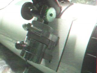
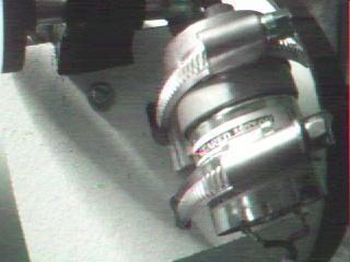
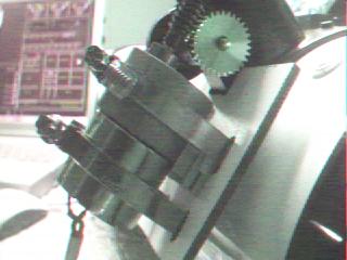
I use 2 jubilee clips now to control the tilt of the
motor. I have enclosed some pictures so that you can see
what I did. On all pictures you can see how I attached
the motor at the plastic base. On Fig. 3 you can
see the bracket underneath the motor. It is a bit in de
middle of the motor, so that by tightening/loosening the
jubilee clips I can adjust the tilt of the motor. This
works very nicely.
In the odd case I would like to go to manual operation I
would just have to loosen the jubilee clip closest to the
worm wheel and tighten the other one, so that worm wheel
and cogwheel do not touch anymore.
I am happy that so far it went so well!
Experience Report #4
Now comes the hard part (for me). Electronics …. I know
nothing about it, so I need good handholding. And Peter
Katreniak held my hand! For your convenience I have
written down in layman's terms what I did.
Peter supplied a diagram that I can - more or less - read
(but not understand). You can find the diagram(s) on
Peter's page about the electric focusser.
The idea of the electronics is twofold:
a. To protect the switch, the motor and the relay from
burning contacts and other nasty things. I assume that
has to do with little sparks that decrease the lifetime
of the components.
b. To reduce the motor speed by 50%, controlled by a
switch, so that focussing can be even better!
Although I think Peter will supply a list of what to buy
but I also give it here:
6 diodes 1N4148
1 Zener diode BZXB5V006.2 or another Zener diode with 6.2V
Zener voltage and power 1.3W
1 condenser 100V
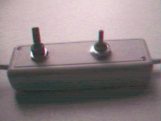
1 on/off switch to control the speed (I have chosen a
toggle switch, so that I can feel the position the switch
is in)
Total costs (in The Netherlands) approx US$ 4,-- so
almost nothing.
PROTECTION
Look at the diodes carefully: they have a
dark or black stripe on one end: that stripe is the same
one as you can see in Peter's diagram
(the diodes are the things with a triangle and a vertical
line or stripe). Make sure you mount the diodes pointing
into the correct direction: they are polarity sensitive.
When soldering the diodes you also have to take care that
they do not get too much heat: best is to use a tool (tweezers)
and hold that between the body of the diode and the
soldering and: this way you can absorb the heat before it
hits the diode itself.
The positive pole (the plus) is on top of the diagram.
Make sure you make no mistakes with the polarity!!
The condenser must be soldered over the 2 contacts of the
motor itself (no polarity here…)
SPEED CONTROL
The Zener diode must be put 'over' the new switch, if
effect bypassing the switch. The speed control is based
on the principle that the electricity always takes the
easy way.
When the switch is in ON position the current takes the
easy way: straight through the switch. However, when the
switch is OFF, the electricity has only one way to go:
via the Zener diode, and only 50% of the electricity can
get through the Zener diode, so instead of 12 Volt the
motor only gets 6 Volts. Voila: speed control.
I expect that - in low speed -the total travel time from
total IN to total OUT (on my scope) now to be 50 seconds
(I did not measure yet). I noticed that - when I manually
give short pulses with the UP/DOWN switch - the focusser
moves in very small steps.
PERFORMANCE
The total travel distance (from top to bottom) of the
focuser of my scope (a TAL-2M) is 28 millimetres.
At normal speed this is covered in 25 seconds or 1,12 mm
per second.
At low speed it takes 44 seconds or 0,64 mm per second.
I was interested to know what was the smallest 'step-size'
I could achieve in low speed operation, so I manually
gave 100 short pulses by using the switch and then
measures the distance covered by the focusser :6
millimetres. This means a step-size of 0,06 millimetres,
which I feel is quite nice for fine focussing.

Fig. 1 |

Fig. 2 |

Fig. 3 |

Fig. 4 |
Visit directly Jan's web
site
Back to Homemade Electric
Focuser page
Computer generated images,
real images, drawings and texts are property of the
author and may not be reproduced or used without
permission of author.

Last Update: 9.12.2001
|