| Philips
Vesta (PCVC675) LONG EXPOSURE cooled SC2 camera A,
Introduction
B,
Technical data
C, Peltier cooling system power
requirements
D, Detailed photo-documentation of
modification
E, Electronic thermostat
Introduction
After five months of using my Philips
Vesta 675SC camera I decided to modify it to stage 2 (software
switching long exposure mode, switching CCD amplifier on/off)
with cooling. The inventor of this modfication is Steve
Chambers and you can find on his pages schematic
diagram and information about this modification. The
cooling system was built according to nice idea of Peter
Vasey.
!WARNING! You can use the following
information on your own risk. Author is not responsible
for any damage of camera or computer equipment. The
following procedure was done successfully by author, but
he cannot guarantee, that your modification will be
successful.
Technical Data
Weight
(incl. USB cable) |
309g
(non modified Vesta has 175g)
|
Dimensions
(length x width x height) |
90mm x
65mm x 40mm (without radiator)
90mm x 65mm x 80 mm (with radiator) |
| Maximum usable exposure time |
15-20
min |
Temperature difference
(difference between ambient temperature
and temperature of alloy chamber arround CCD) |
~28°C |
| Cooling down time |
8-10
min |
DarkFrame
(15min, gain 100%, white balance - Indoor,
cooled, ambient temperature 25°C) |
 |
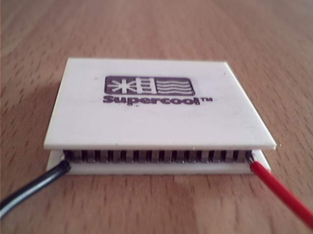
Peltier Cooling System
Power Requirements
Peltier unit - Supercool
PE-127-10-25
| Imax |
2.0 A |
| Umax |
16.4 V |
| PCmax |
19.3 W |
| DTmax |
74 °C |
| THot max |
80 °C |
Dimensions
(l x w x h) |
30mm x 30mm x 4.8mm |
|
| Voltage |
Current consumption |
Power consumption |
| 12V |
1.26A |
15.12W |
| 9V |
0.96A |
8.64W |
| 6V |
0.63A |
3.78W |
| 5V |
0.46A |
2.30W |
| 4.5 |
0.39A |
1.75W |
Note: Power consumption was measured with
ventilator switched ON.
Detailed photo-documentation of
modification
Detailed description of procedure of modification
camera for Peltier cooling you can find on Peter
Vasey web site.
Here you can find detailed photos, which illustrate, who
the modifaction was done.
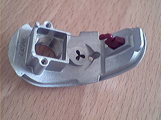
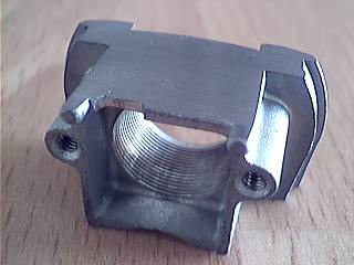
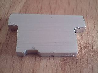
Alloy casting housing the LED, Microphone, CCD
Chip and lens. Note that end part of PCB carrying
only model information was trimmed off. |
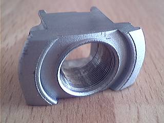
Detail view of alloy part, which must be cut down
to cube. |
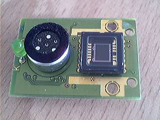
Truncated PCB with CCD, microphone and LED.
The with of module is 20mm. |
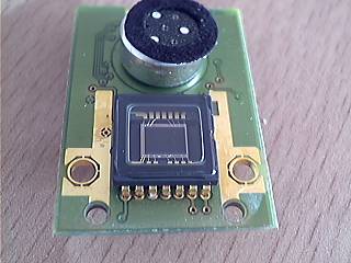
Another look at CCD. The second pin from left
must be cut. |
Detail of hand-worked alloy part. Abrasive paper
'400' was used for final treatment. |
Detail from PCB side. Note the small recess on
the left side which has been cut to allow the
passage of a wire from cut CCD pin 9. |
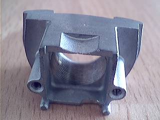
Another side of alloy part. The recess is for
microphone. |
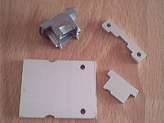
Hand-made aluminium parts for cooling system
together with alloy box. |
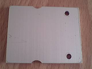
Detail vie of aluminium plate, which is connected
to cold side of Peltier unit |
Small spacer between aluminium plate and alloy
box. |
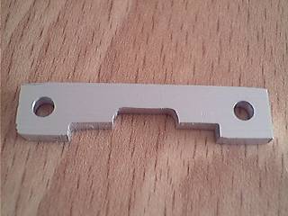
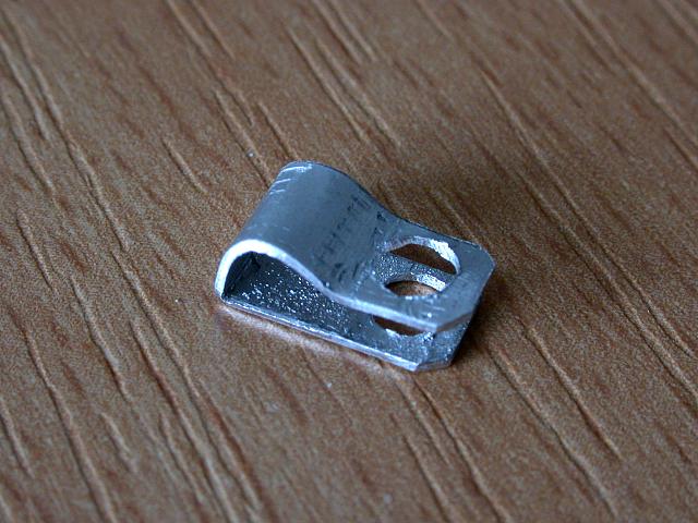
Small clamping plate for gripping alloy box to
aluminium plate. |
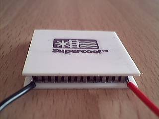
Peltier module (Supercool PE-127-10-25) |
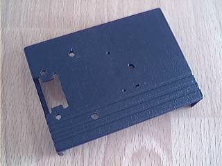
Top view of plastic case with filed out openings. |
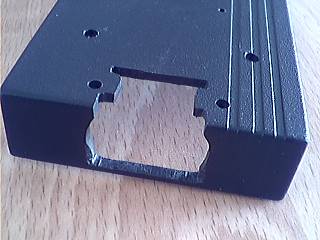
Front view of plastic case with detailed view of
opening for alloy box with CCD unit. |
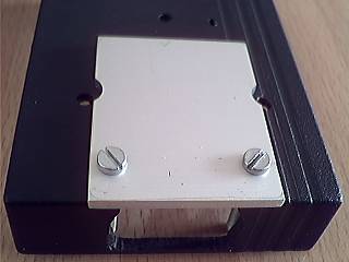
Aluminium plate attached to plastic box |
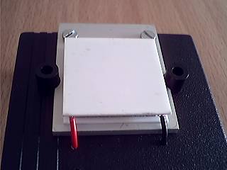
Cold plate with Peltier unit. Note black plastic
spacers on both sides of aluminium plate. |
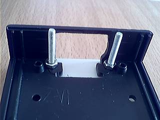
View from inner part of plastic case |
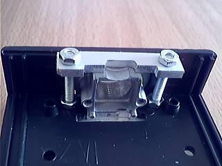
Gripping of alloy box part by means of clamping
plate and bolts |
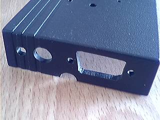
Rear side with holes for connectors and LED |
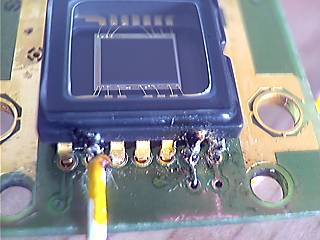
Cut pin 9 of CCD.
Unfortunately, I had a bad day - I cut the pin 13
accidentally. You can see repair on right side |
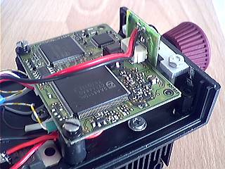
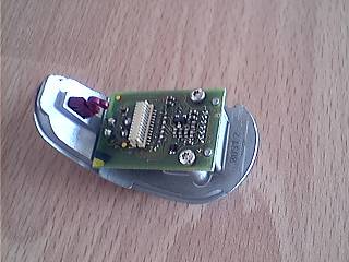
Camera's main board mounted into case |
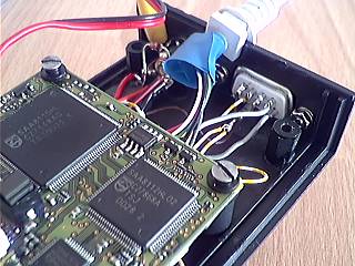
View of connector part situated on rear side |
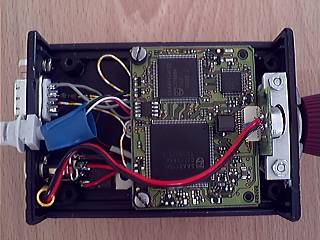
Top view of inside parts |
Switching transistor of SC2 modification is
soldered directly to CCD's PCB (prevention from
unwanted interference). Note green 2k7 resistor |
| |
|
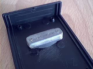
Metal part from Vesta camera with tripod thread
was modified for attaching to bottom part of case |
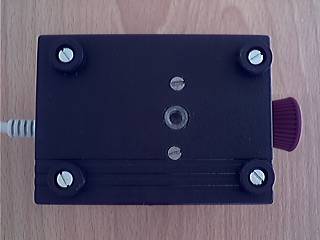
Bottom part of case with tripod thread |
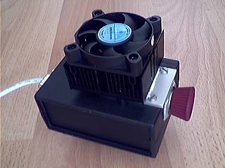
The final result |
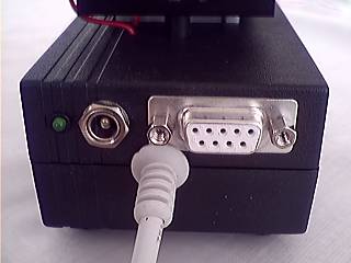
Rear side of camera - green LED (from CCD PCB),
connector for 12V power for Peltier unit and
ventilator, CANON 9 connector for computer
control and USB cable |
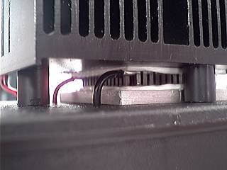
Detail of Peltier unit with radiator |
Ice created on cooled metal parts after 1 hour of
cooling. (Ambient temperature 26°C) |
Electronic thermostat
The Peltier cooling system of my webcam
is able to generate temperature difference about 28°C (between
ambient temperature and temperature of cold chamber). It
is very powerful cooling. But there may be a problem in
colder nights, when cold chamber can become too cold. In
freezing nights it is not a problem to get tempereture of
-30°C or even lower, which is even under allowed storage
temperature!
According to SONY datasheet the CCD chip used in Philips
Vesta cameras (ICX098AK) has the following temperature
conditions:
| Storage temperature |
–30°C to +80°C |
| Operating temperature |
–10°C to +60°C |
I decided to design an electronic
thermostat, which would protect the CCD from very low
temperatures.
The thermostat should satisfy the next demand:
1, Low power loss (i.e. low production of heat)
2, Small size and weight - the best solution would be to
put the electronics into camera case
3, Adjustable temperature threshold
4, Precision about +/-1°C
The most difficult criteria are 1, and 2,. The problem is
to switch the current about 1-1.5A without loss of power.
I tried several solutions - bipolar switching
transistors, relays - but without success. In case of
inbuilding thermostat in camera case, it is unwelcome for
electronics to generate additional heat. Finally I
decided to use power MOSFET. The IRFR024N type has the
resistance in on-state 0.075Ohm. It enables to achieve
power loss only 75mW (1A current).
The costs of the whole electronic thermostat is not more
than 5,-Euro.
Here is my final version of thermostat for Peltier
cooling system:
Click the
picture to see full-sized schematic diagram.
Note: Supply
voltage is 12V. Inputs of the second operational
amplifier must be handled (+ input to VCC, -
input to GND) to avoid its oscillation. |
The principle of function:
The temperature sensor IC2 (LM335) generates voltage
which represent temperature (10mV/K). The voltage from IC2
is compared with voltage adjusted by R8 trimmer. IC3a (one
half of LM393) serves as comparator. R11 and D1 provide
hysteresis of the control loop. The hysteresis is
necessary for securing the transistor T1 (IRFR024N) is
working in switching mode (only in this mode the power
loss is very low). D2 LED is indicating that Peltier is
switched on (I like blue LED for indication of cooling ;-))).
The contruction notes:
I built the module on experimental piece of PCB. I
protected the temperature sensor from water/ice by
putting its end with pins into heat-retracting insulator
(see a picture below). The voltage from IC2 is led out to
connector on rear camera panel. It enables me to measure
temperature of cold chamber.
As the thermostat consists of the sensitive measuring
part and power switching part, the PCB must be carefully
designed. You must pay attention for current loops - you
have to design two separate grounds for each part. In
case of violation of this rule, the thermostat will not
be sufficiently accurate.
The adjustment procedure:
At first it is necessary to do fine
adjustment of IC2. I used mixture of water and ice (which
has temperature 0°C while ice is not melted). I put the
temperature sensor into this mixture and by means of
trimmer R7 I set the voltage on the IC2 (between cathode
and anode) to 2.731V (which represents 273.1 Kelvins).
Then I set the voltage in R8 trimmer according to
required temperature - in my case I set 2.551V, which
represents -18°C. With current values of R2, R4 and R8
it is possible to set the temperatures between -19° - +2°C.
That's all.
According to my tests the termostat is holding the
temperature in required range -18° +/-1°C.
And here are some photos of implementation of the
thermostat:
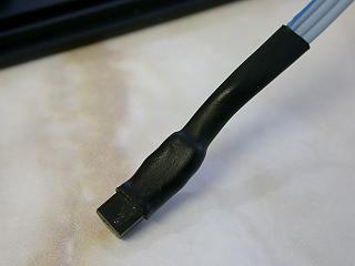
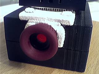
The temperature sensor (LM335) put into heat-retracting
insulator |

The holder of temperature sensor (made from piece
of plate) with hole for M3 bolt |
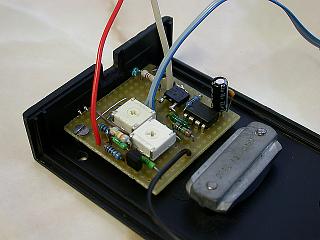
The thermostat electronics built in bottom side
of camera's case |
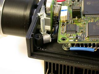
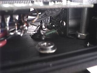
Fixation of sensor to cold chamber. The sensor is
fixed under M3 nut. |
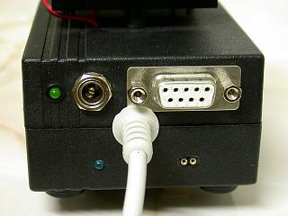
The rear panel of camera. Notice the bottom part:
On the left side there is a blue LED (Peltier
indicator) and on the right side there is a
connector for measuring temperature (by means of
digital multimeter). |
|
Have
a look at tests of my cooled SC2 camera
Back to Astro Photography
page
Computer generated images,
real images, drawings and texts are property of the
author and may not be reproduced or used without
permission of author.

Last Update: 14.09.2005
|