| Philips
Vesta (PCVC675) LONG EXPOSURE modification At
the first place I want to thank to Steve
Chambers for his excellent job on
long exposure modification of webcams. As a tribute to
his work the QCUIAG settles to use SC designation for
modified cameras. So my Vesta 675 webcam after
modification will become Vesta 675 SC. Also I want to
thank to all people in QCUIAG,
who participate on long exposure modification project.
| COPYRIGHT
NOTICE! The inventor and
author of the modification is Steve
Chambers. The author is
asking that the information about modification is
not used by others for personal gain. Any
individuals or companies wishing to produce
commercial products based on these modifications
please contact Steve Chambers directly.
For more information read the Copyright
paragraph. |
!WARNING! You can use the following
information on your own risk. Author is not responsible
for any damage of camera or computer equipment. The
following procedure was done successfully by author, but
he cannot guarantee, that your modification will be
successful.
!NEW! (1.4.2002) I
modified my SC1 modified webcam to cooled SC2 webcam.
Look here.
1, Preparation works
Link for studying SC modification:
1, Steve
Chambers - Inventor of the modificaton
2, Bob
White - Step by step modification procedure with nice
pictures
3, Sylvain
Weiller - Excellent pictures, step by step procedure
(french)
2, Schematic diagram
After studying a
lot of designs in QCUIAG mailing list I decided to do
modification according to the next schematic:
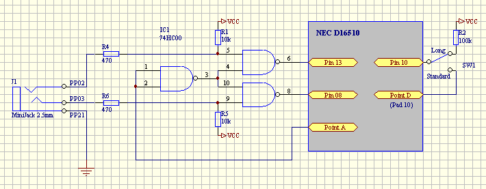
Note: Point A and Point D connections are evident
from "Dead bug" schematic diagram bellow.
This solution is prepared for Self-Guide mode of
webcam for future, while beeing compatible with the
current modification. The only thing needed for
compatibility is to connect wires from R4 and R6 on CANON25
connector side. But it is necessary only for
compatibility with Desire software. AstroSnap and K3CCDTools software enable to set
the data byte for activation and deactivation long
exposure.
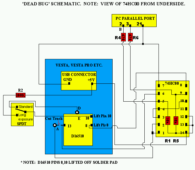
The next picture shows a diagram of deadbug method of
modification. It is modificated (according to schematic
above) diagram based on Peter's Vasey diagram.
3, Tools
Because the modification work is like a
micro-surgery, it requires some special tools for work.
The camera parts are based on CMOS technology, so the
parts can be easily damaged with static electric charge.
The very delicate SMD technology requires using special
solder iron for electronics with thermo-regulator. NEC D16510
integrated circuit has pin distance 0.65mm, so it is
necessary to have needle-shaped soldering tip. Very fine
work work requires using magnifying glass. I bought
especially for the modification the special helping hand
with magnifying glass (only for 5$). I think, that it is
impossible to do the job successfully without it. For
cutting the via to pin 13 and to scraping off the green
protective coating the cutter is needed.
The list of tools:
- solder iron with thermo regulator + sharp thin
soldering tip
- helping hand with magnifying glass
- cutter
- the steel guitar string "e"
- jewlers screw drivers
- Patex glue heat gun (for fixing wires on the printed
circuit board (PCB))
- patient wife ;-)
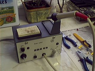
Solder iron with thermo regulator |
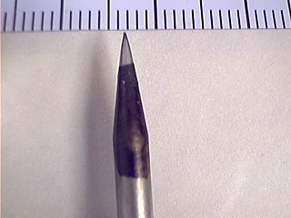
Very sharp soldering tip (less than 0.2mm) |
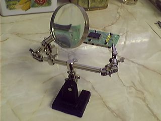
Helping hand with magnifying glass |
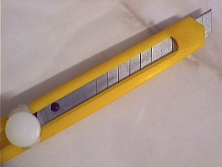
The cutter |
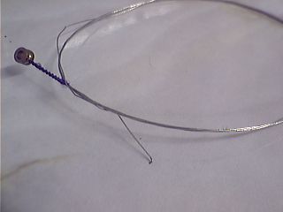
Hook prepared from steel guitar string "e" |
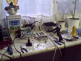
My "kitchen workplace" |
4, The modification
itself
I followed the very good description of Bob White
Step by step instructions, but some steps I did by my own
way.
a, Taking the camera apart.
I used a pocket knife and jewlers screw
driver for this job. For learning this step, look at Sylvain
Weiller's page.
b, Mounting 2.5mm
minijack socket and switch to the camera case.
I did this step before the whole
modification in order to have prepared all things after
the modification work. After such delicate work a man is
very often impatient to try the result of work and have
no time for mechanical job. Be carefull to locate the
parts not to collide the printed circuit board.
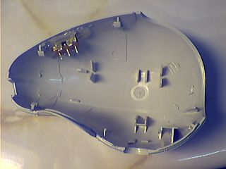
Left cover with glued switch. |
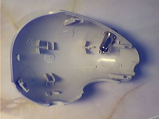
Right cover with mounted 2.5mm minijack socket |
c, Scraping off the
green protective coating and lifting the pin 10 of D16510
Unplug USB socket and CCD part of camera
from the main camera board. Scrap off the green
protective coating from the pin 10 and pin 8 & 13
vias according to Bob White
step by step instructions. Lift the pin 10 of D16510. For
this very fine work I prepared a tool from an old steel
guitar string "e" - special hook. I put this
hook under the pin 10, warmed the pin with solderer and
gentle lifted up the pin. Be carefull not to break off
the pin.
The first test:
After that I folded up the main board, USB and CCD and
check the functionality of the camera. If the work was
successfull, the video capture program must work, but the
exposure must be independent on shutter speed. If the
exposure is dependent on shutter speed, then the pin 10
is touching the pad below pin 10.
d, Cutting via from pin
13
Unplug USB socket and CCD from the main
board, again. Look at Bob White
instructions, because all steps are refered to his
pictures and documentation. Cut the via from pin 13 with
the cutter. Be careful not to cut the close vias from the
neighbour pins. Don't cut too deeply, because PCB is
multi-layered. Solder wires of suffcient length to points
A and D. I found out that this step was much more
difficult for me than lifting the pin 10. The solder area
in points A and D are very small, so it is difficult to
get a tin to them.
e, Preparing a dead bug
74HC00 integrated circuit
Prepare a deadbug from 74HC00 integrated
circuit accotding to above deadbug schematic diagram.
Glue the chip by means of double sided sticky tape to the
main board (on D16510 side).
f, Making connections
Solder a wire from point A to pin 1 of 74HC00.
Solder another wire from pin 13 of D16510 (take care to
avoid from connecting the cutted via). Make connection
from pin 1 of USB connector (+5V - red wire) to pin 14 of
74HC00. Make another connection from pin 4 of USB
connector (ground - black wire) to pin 14 of 74HC00.
g, Preparing paralell
port connector (Canon DB25)
I used bifilar shielded cable (for audio
devices) for connecting the camera to the PC paralell
port. I used two 150ohm protective resistors directly
inside the connector connected in to pins 2 and 3 (they
are not in the schematic diagrams above). They protect
paralell port of computer, when you plug or unplug
minijack connector to the camera . The opposite sides of
resistors are soldered to the inner conductors of cable.
Solder a shield to pin 21 of Canon connector. Solder the
opposite sides of cable to resistors R4 and R5 on deadbug.
The second test:
Plug USB socket and CCD to the camera main board. Plug
Canon connector to paralell port and camera to USB. The
camera is fully functional for long eposure now. You can
test it with Desire or AstroSnap software now. If
something is wrong, test all things done from the point
d, to g,.
h, Modifying camera for
autotracking functionality
Lift the pin 8 of D16510 using the same
technic like in point c,. Solder a wire connecting lifted
pin 8 of D16510 to pin 8 of 74HC00. Solder another wire
to lifted pin 10 (the second side of it will be soldered
to switch in next step).
The third test:
I decided to do another test, to find out that D16510 was
not damaged by soldering and lifting the pin 8. I tested
the camera with AstroSnap software, because it allows to
set the control bytes for paralell port.
i, Completing the
modification
Unsolder cable (leading to Canon DB25
connector) from R4 and R5 resistors on deadbug and solder
the cable to minijack 2.5mm. Solder wires connecting R4,
R5 and ground with 2.5mm minijack socket on camera case.
Solder wires connecting the pin 10 of D16510 and Point D
with switch on camera case. Check all connections and
close camera case. Take care to not cut wires, while
closing the case.
The fourth test:
Test all function of camera (including standard mode).
If all tests were completed successfully, then
the camera is ready for astro imaging. Congratulations!
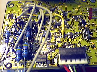
The deadbug on left and USB connector on right |
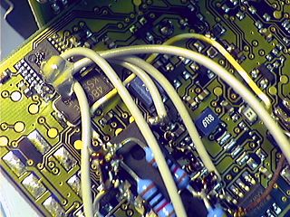
NEC D16510 IC and glued wires on it |
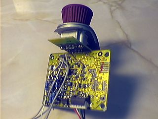
The overall look at the camera PCB after finished
job. |
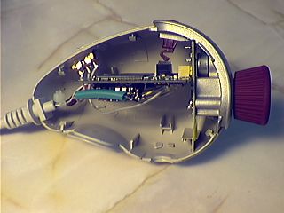
Almost all work done. |
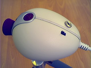
The final result |
|
Steve Chambers made also
another modification - SC2. It allows to achieve longer
exposures (up to 20 minutes) by switching off CCD
amplifier during long exposures and therefore reducing
CCD glow. The modification is useful only if you intend
to do longer exposures than 30s. It also requires proper
CCD chip cooling (reducing hot pixels). For more details
check Steve's
web page.
!NEW! (1.4.2002) I modified my SC1 modified webcam
to cooled SC2 webcam. Look here.
Have
a look at tests of modificated camera
Back to Astro Photography
page
Computer generated images,
real images, drawings and texts are property of the
author and may not be reproduced or used without
permission of author.

Last Update:
14.09.2005
|